Extended configuration
General
The extended configuration of the FLS-M is carried out by setting the pins on the DIP switch (2) and by loading a configuration file via USB (5).
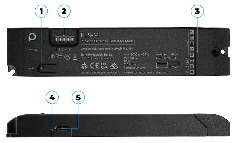
- Different LED types can be connected to the FLS-M. The additional setting on the DIP switch is necessary so that the LED channels can be assigned correctly in the Matter App. Additional configurations can only be enabled with the Config-Builder.
Any change to the DIP switch will only take effect after the power supply has been disconnected.
Radio protocol
The FLS-M supports both Matter over WiFi and Zigbee 3.0. The radio protocol used is determined via the DIP switch position 1.
| DIP | Radio protocol | LED type | Endpoints | Description |
|---|---|---|---|---|
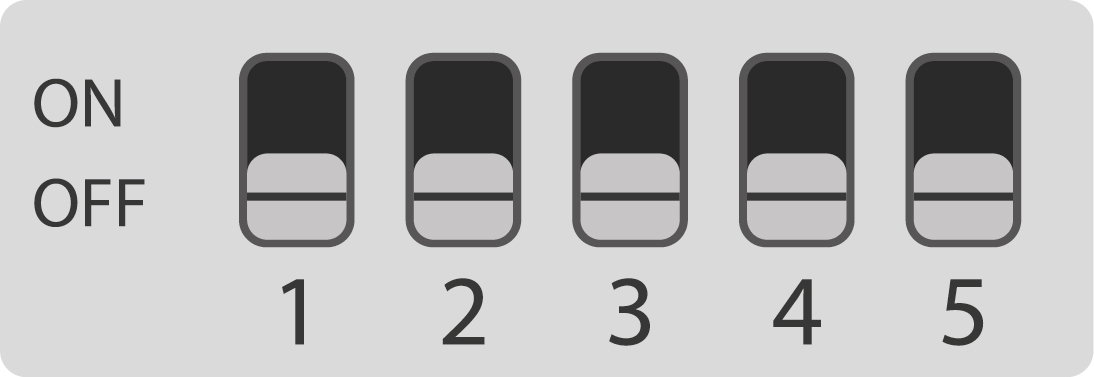 |
Matter WiFi | RGBW | 1 | Factory setting |
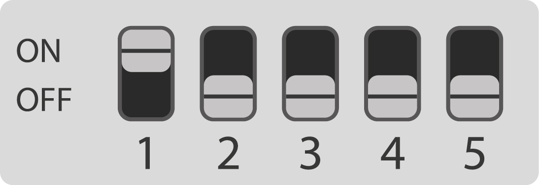 |
Zigbee | RGBW | 1 |
LEDs
The FLS-M can work with both classic LED strips and individually addressable LEDs.
Classic LED strips
- common anode
- constant voltage DC 5V, DC 12V, DC 24V
- dimmable via PWM
- RGB (red, green, blue)
- RGBW (red, green, blue, white)
- RGB+CCT (red, green, blue, warm white, cold white)
- single-color LED strip
- CCT (warm white, cold white)
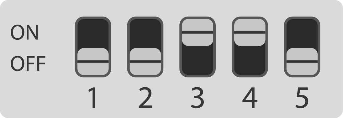
| DIP | Radio protocol | LED type | Endpoints | Description |
|---|---|---|---|---|
 |
Matter WiFi | RGBW | 1 | Factory new |
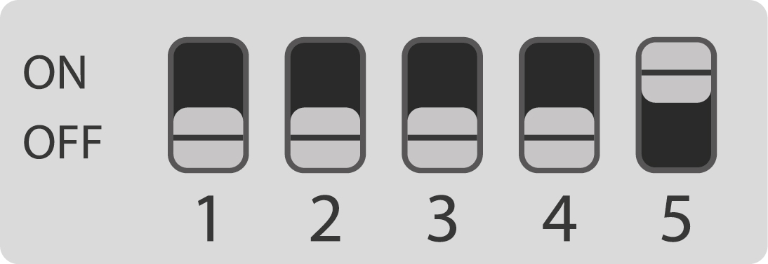 |
Matter WiFi | RGB | 1 | |
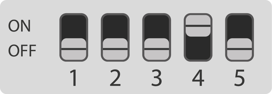 |
Matter WiFi | RGB + CCT | 1 | |
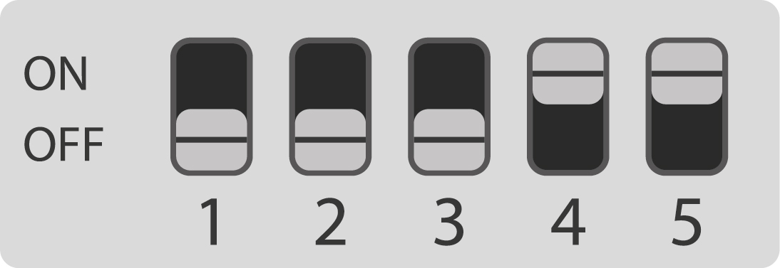 |
Matter WiFi | Single | 1 | |
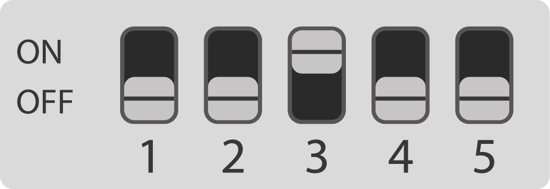 |
Matter WiFi | Single | 5 | Each strip can be controlled separately |
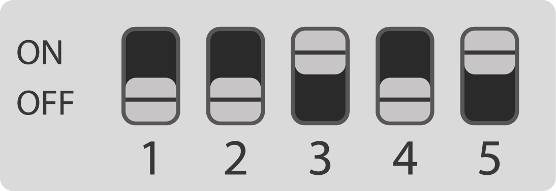 |
Matter WiFi | RGB + CCT | 2 | RGB and CCT can be controlled separately |
 |
Matter WiFi | CCT | 1 |
Individually addressable LED strips
- LEDs with LED controller such as WS2811, WS2812, WS2812B, WS2813, WS2814, WS2815, TM1814, SK6812
- constant voltage DC 5V, DC 12V, DC 24V
- Controllable via data line
- RGB (red, green, blue)
- RGBW (red, green, blue, white)
- up to 1024 individually controllable LEDs possible
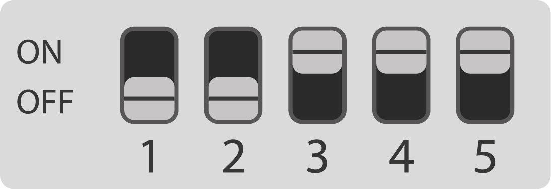
| DIP | Radio protocol | LED-Typ | Endpoints | Description |
|---|---|---|---|---|
 |
Matter WiFi | RGB addressable | 1 | 1024x LEDs |
In certain combinations, both classic and individually addressable LED strips can be used at the same time. These can only be created with the Config-Builder.
Currently, only static control of individually addressable LEDs is possible. No effects are supported yet.
USB interface
The FLS-M can be configured via the USB-C interface and programmed with new software.
A USB-C data cable must be used!
- Disconnect the FLS-M from the external power supply unit or switch off the power supply unit
- Connect the FLS-M to the PC/laptop via USB-C
- Open external program and search for connected FLS-M
- Activate connection
- Select and update new firmware
- Load new config file from the Config-Builder
The Web Serial API protocol required for configuring is only supported by Chrome, Edge, and Opera. An overview of supported browsers is listed here: https://developer.mozilla.org
When using the USB-C, the FLS-M must be disconnected from the external power supply unit or the power supply unit must be switched off.
If the FLS-M is connected via USB-C, only the microcontroller is supplied with power. The LED driver is not controlled. No LEDs can be switched on.
Color matching
When LED strips from different manufacturers are used at the same time, differences in the perceived result often occur when setting the same color or color temperature.
The FLS-M allows you to specify the characteristics of the LED light source used. This is taken into account in the color mixing algorithm and enables a much more precise color representation of the desired colors.
- The individual color values for red, green, blue and white are specified in the XY color space
- The brightness is shown as intensity
- The configuration is done in the Config-Builder
When manually matching without tools or measuring devices, the reference light or LED strip must be placed next to the LED strip to be adjusted.
We recommend placing the strips so that you only see the light emitted, e.g. on a white wall, and do not look directly into the LED.
Practical examples
Each RGB LED consists of sub-LEDs in the colors red, green and blue. The relative brightness of the respective sub-LEDs is specified as intensity. If a sub-LED is darker than the others, it must have an intensity of less than 1.
- If the color yellow is shifted to green, the intensity of the red LED must be lowered, as the mixing algorithm assumes equally bright red and green sub-LEDs
- If the color pink is shifted too far to red, the intensity of the blue LED must be lowered, as the mixing algorithm assumes equally bright red and blue sub-LEDs
- If the color cyan is shifted too far to blue, the intensity of the green LED must be lowered, as the mixing algorithm assumes equally bright blue and green sub-LEDs
Summary
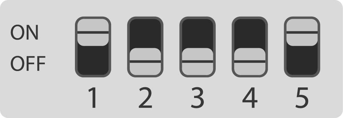
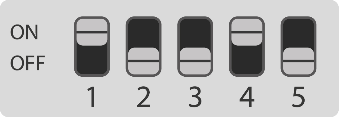
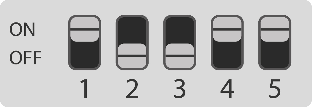
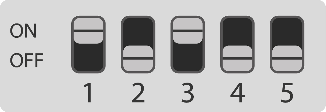
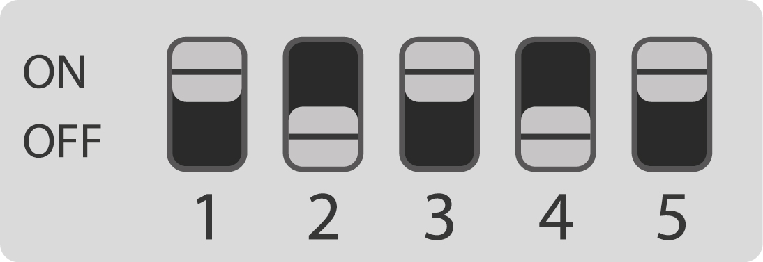
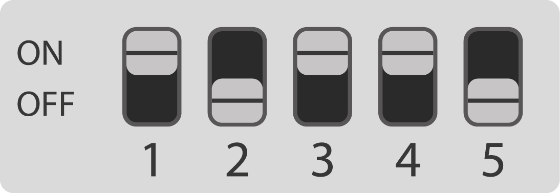
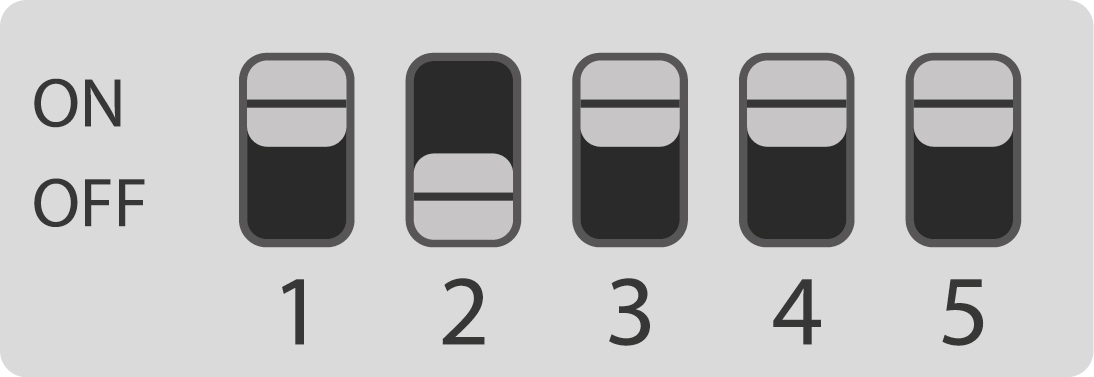
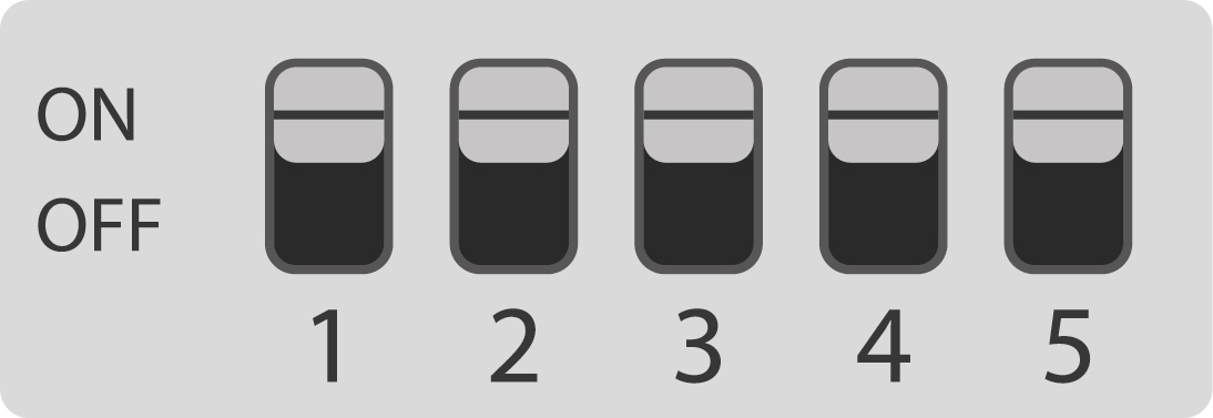
The following table shows the options that can be set using the DIP switch.
| DIP | Radio protocol | LED type | End points | Description |
|---|---|---|---|---|
 |
Matter WiFi | RGBW | 1 | Factory new |
 |
Matter WiFi | RGB | 1 | |
 |
Matter WiFi | RGB + CCT | 1 | |
 |
Matter WiFi | single | 1 | |
 |
Matter WiFi | single | 5 | Each strip can be controlled separately |
 |
Matter WiFi | RGB + CCT | 2 | RGB and CCT can be controlled separately |
 |
Matter WiFi | CCT | 1 | |
 |
Matter WiFi | RGB / RGBW addressable | 1 | 1024x LEDs of type WS2811, WS2812, WS2812B, WS2813, and WS2815. Any settings other than these must be created using the Config-Builder. |
 |
Zigbee | RGBW | 1 | |
 |
Zigbee | RGB | 1 | |
 |
Zigbee | RGB + CCT | 1 | |
 |
Zigbee | single | 1 | |
 |
Zigbee | single | 5 | Each strip can be controlled separately |
 |
Zigbee | RGB + CCT | 2 | RGB and CCT can be controlled |
 |
Zigbee | CCT | 1 | |
 |
Zigbee | RGB / RGBW addressable | 1 | 1024x LEDs of type WS2811, WS2812, WS2812B, WS2813, and WS2815. Any settings other than these must be created using the Config-Builder. |
 |
- | - | - | Customized configuration* |
The configuration file created by Config-Builder and loaded via USB is accepted.
Config-Builder
Click here for the FLS-M Config-Builder.
For the customer-specific configuration to be effective, the
Customer-specific configuration
mode must be set
on the DIP switch.
| DIP | Description |
|---|---|
 |
Customized configuration |
What can the Config-Builder do?
- Setting the radio technology
- Setting the PWM frequency
- Setting the channel assignment of each individual color
- Setting the color balance in XY format for each individual color
- Creating own dimming curves (e.g. Dim-TO-Warm)
- Creating LED segments and areas for individually addressable LED strips
- Creation of animations
- Using classic and individually addressable LED strips at the same time
- Naming all created lights
- Downloading and saving a configuration from an active FLS-M
- Creating and saving a configuration without a connected FLS-M
How it works for non-addressable LED strips
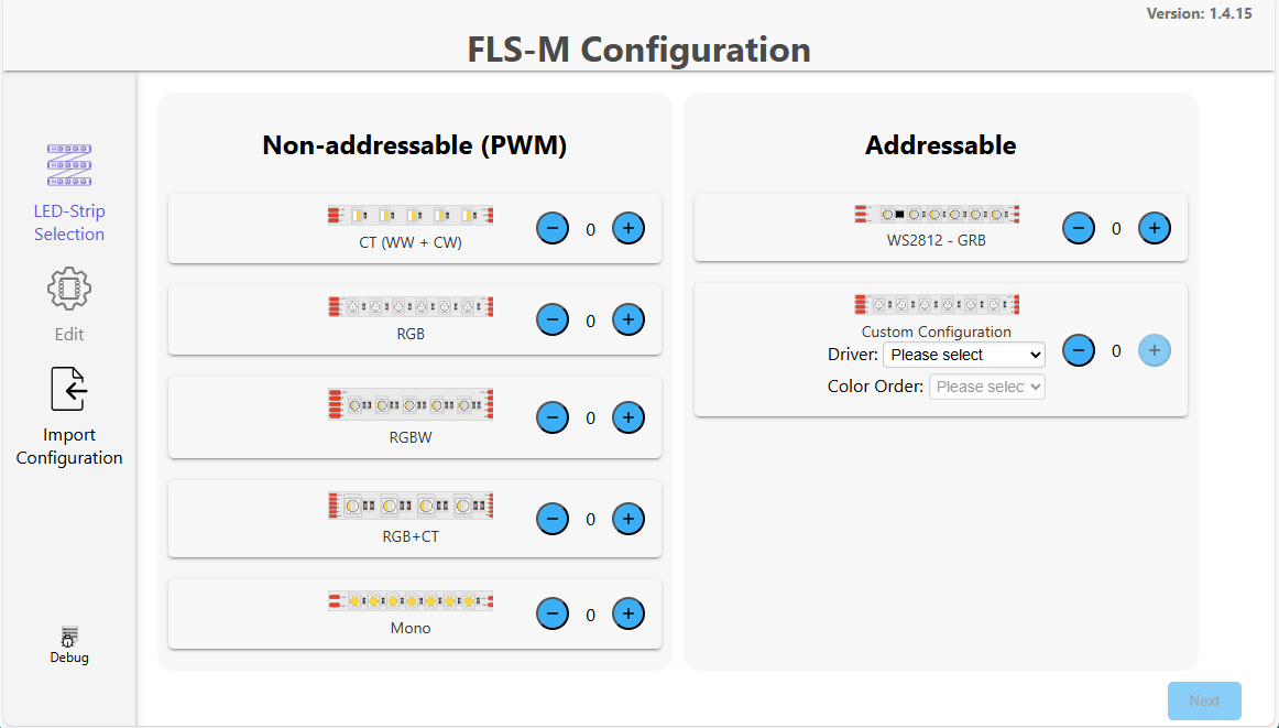
Selection of non-addressable LED strips:
- RGB, RGBW, RGB+CCT: maximum one colored LED strips
- CCT: maximum two CCT LED strips
- RGB + CCT: one LED strip each
CCT
RGB
RGBW
RGBCCT
RGB + CCT
2x CCT
RGB, RGBW and CCT in combination with monochromatic LED strips:
RGB + Single
RGB + 2x Single
RGBW + Single
2x CCT + Single
Monochromatic LED strips from one to a maximum of five LED strips:
Single
2x Single
3x Single
4x Single
5x Single
Selection of radio protocol:
- Matter over Wifi
- Zigbee 3.0
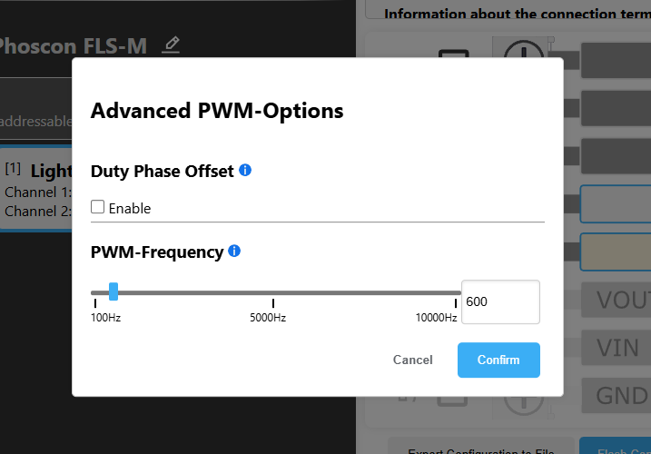
Change PWM frequency if necessary:
- Default setting is 600 Hz
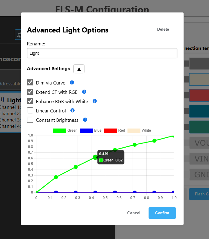
Advanced light options:
Dimming via user curve
- Each light channel has 8 dimming values available
- X-axis: brightness control
target
from 0 to 100% - Y-axis: brightness control
actual
from 0 to 100%
Expand color temperature with RGB
- Setting a color temperature (warm white to cool white) can be done via RGB LED.
Complement RGB colors with white
- The displayable white spectrum is expanded by the addition of RGB LEDs. This is particularly relevant when using RGBCCT LED strips.
Linear control
- The LEDs are mixed according to the brightness setpoint, i.e. the dimming curve runs linearly from 0 to 100%.
Constant brightness
- The brightness remains constant when the color changes.
color calibration
- Each color channel can be calibrated via X and Y position as well as intensity.
Determination of channels:
- The connection of the color channels red, green, blue, white or warm white and cold white can be freely assigned within the connection terminal from 1 to 5.
Transfer configuration to the FLS-M
- Depending on the configuration, re-teaching the FLS-M to the gateway is recommended.
How it works for addressable LED strips

Selecting addressable LED strips:
- WS2812 GRB: maximum one addressable LED strip
- custom driver: maximum one addressable LED strip
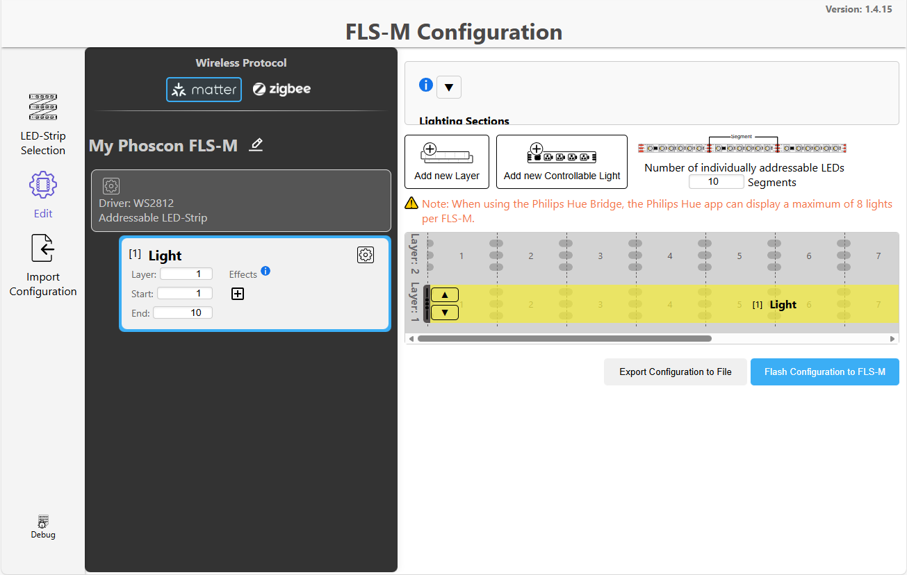
Selection of the radio protocol:
- Matter over Wifi
- Zigbee 3.0
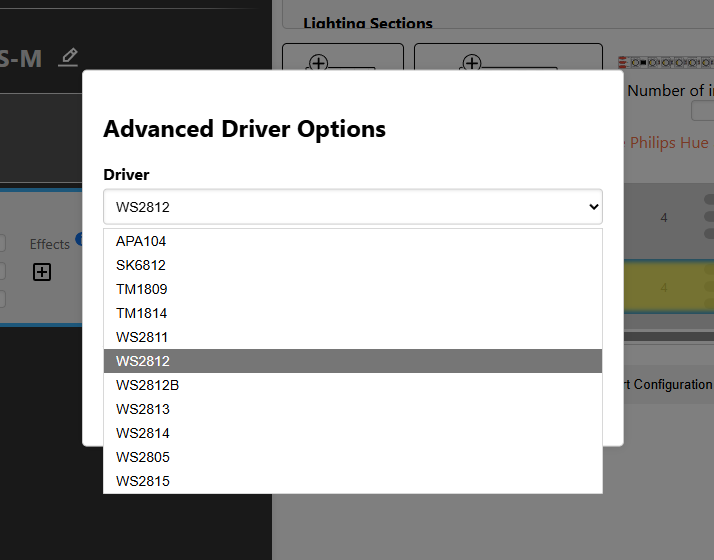
Select driver:
- APA104
- SK6812
- TM1809, TM1814
- WS2811, WS2812, WS2812B, WS2813, WS2814, WS2805, WS2815
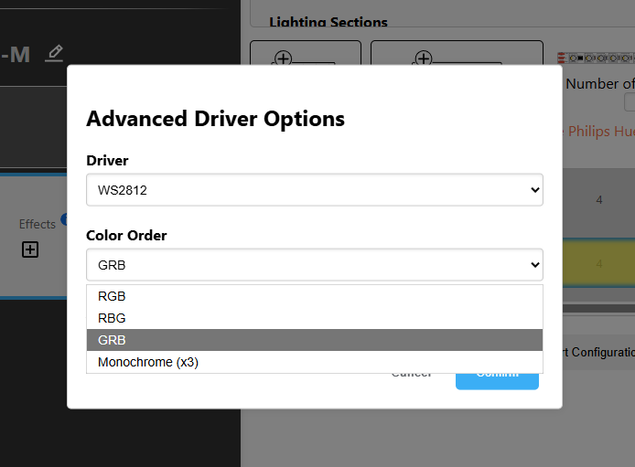
Select color order:
- RGB
- RBG
- GRB
- Solid color 3x
Determine the number and setting of the light:
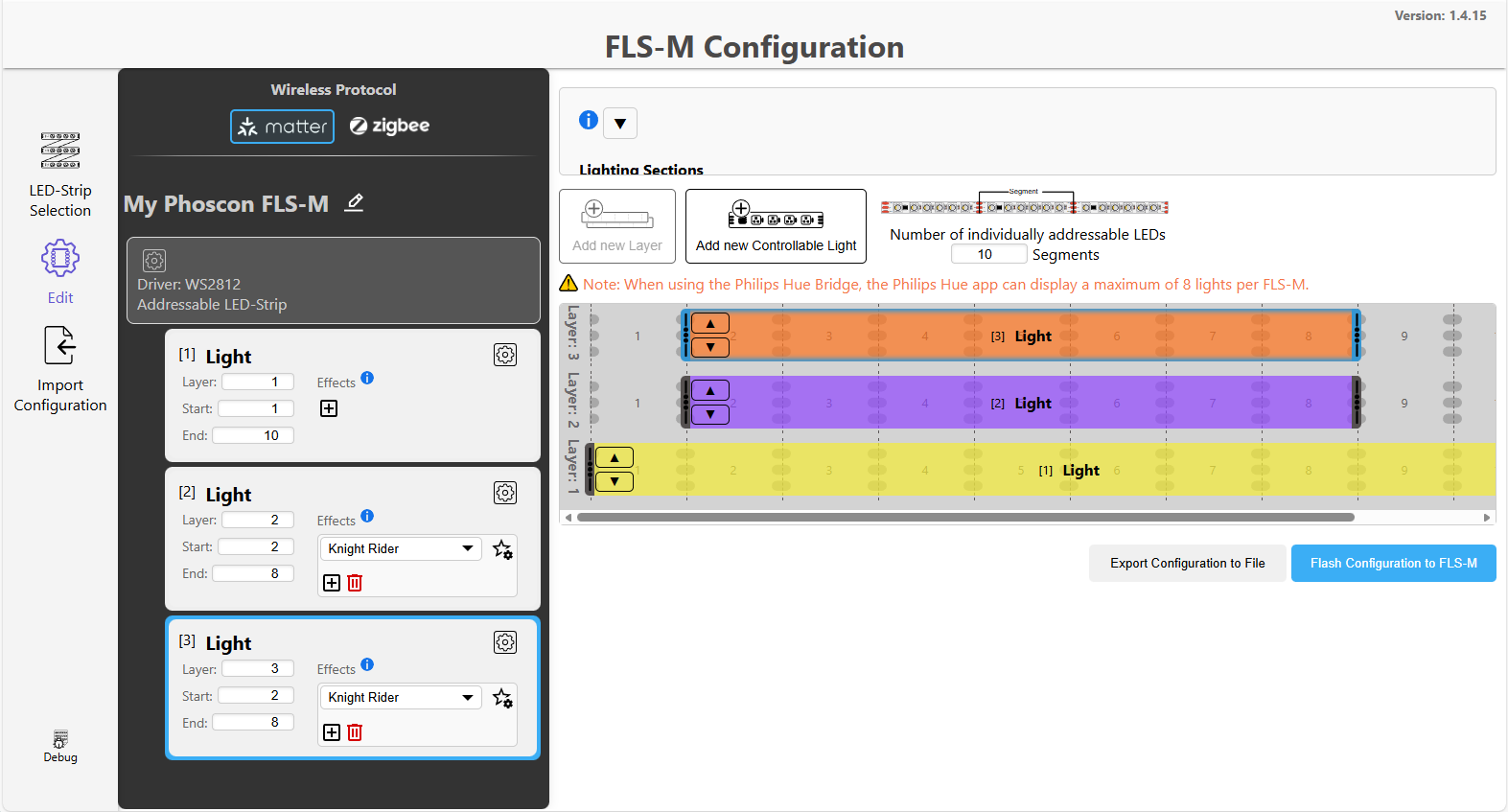
Lighting sections:
- Individually addressable LED strips consist of segments, each with a section edge (scissors symbol) on both sides
- A luminaire is a combination of one or more segments and is displayed in the Matter app as a controllable luminaire
- A maximum of 10 lights can be configured and distributed on up to 3 levels
- Each light can be adjusted in length and position
- The name of each light can be changed to make it easier to identify
- A luminaire on a higher level overlays the luminaire(s) on a lower level
Example:
- Level 3 overlays Level 2 and Level 1
- Level 2 overlays Level 1
Limitation:
- A maximum of 1024 individually addressable LEDs can be controlled
- a maximum of 3 levels possible
- a maximum of 10 controllable lights possible per FLS-M
Use of effects
- Knight Rider (running light)
- Indicator
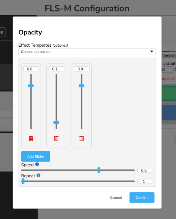
- Opacity
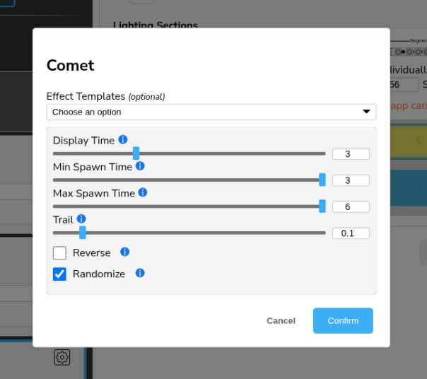
- Comet
- Stars
Each effect can be further configured in detail.
Overview
Knight Rider
(running light)
Indicator
Opacity
Comet
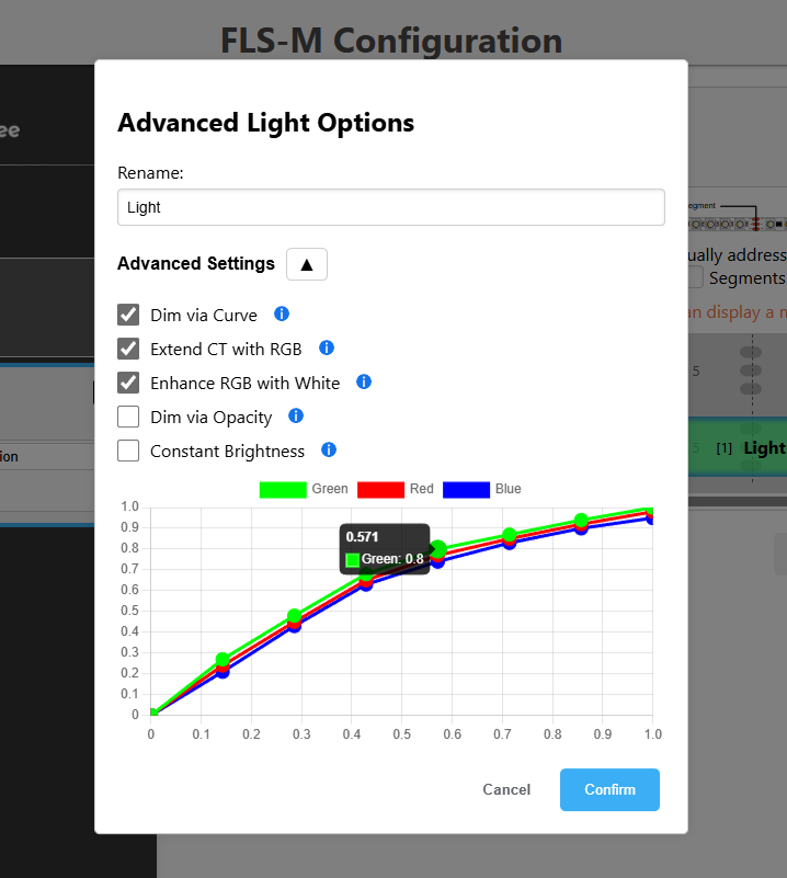
Advanced light options:
Dimming via user curve
- Each light channel has 8 dimming values available
- X-axis: brightness control
target
from 0 to 100% - Y-axis: brightness control
actual
from 0 to 100%
Expand color temperature with RGB
- Setting a color temperature (warm white to cool white) can be done via RGB LED.
Complement RGB colors with white
- The displayable white spectrum is expanded by the addition of RGB LEDs. This is particularly relevant when using RGBCCT LED strips.
Linear control
- The LEDs are mixed according to the brightness setpoint, i.e. the dimming curve runs linearly from 0 to 100%.
Constant brightness
- The brightness remains constant when the color changes.
color calibration
- Each color channel can be calibrated via X and Y position as well as intensity.
Transfer configuration to the FLS-M
- Depending on the configuration, re-teaching the FLS-M to the gateway is recommended.
Combination of non-addressable and addressable LED strips
The FLS-M allows the combination of non-addressable and addressable LED strips on a single device.
Attention:
The connected LED strips must have the same operating voltage.
RGB, CCT and monochromatic LED strips combined with an addressable LED strip:
ALED + RGB
ALED + CCT
ALED + CCT + Single
ALED + Single
ALED + 2x Single
ALED + 3x Single
The respective settings from the previous chapters can be assigned to the lights for non-addressable and addressable LED strips.
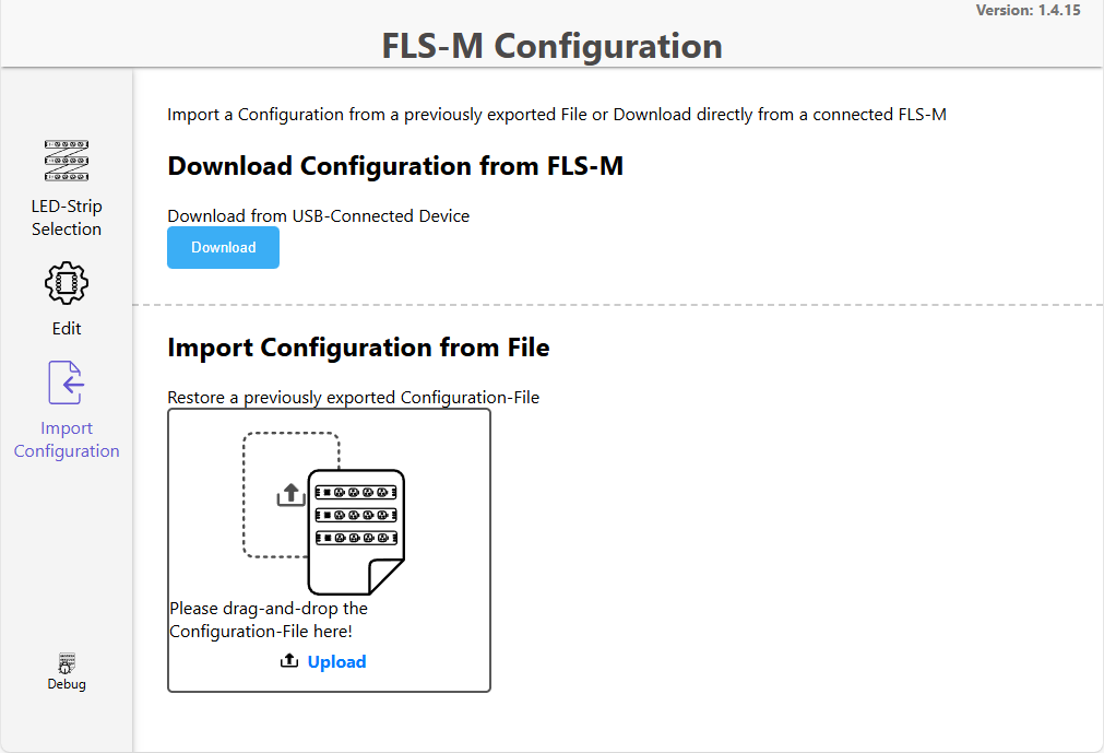
Import the configuration
The current configuration on the FLS-M or a previously created and saved configuration file can be loaded into the Config Builder.
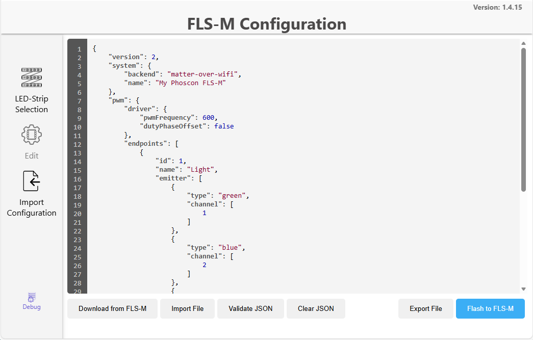
Debug output of the configuration
The set configuration can be displayed in the debug output in JSON format and can also be changed.
- Import a saved configuration
- Validation of JSON data
- Saving the configuration in JSON format
- Transfer configuration to the FLS-M
Examples of animations
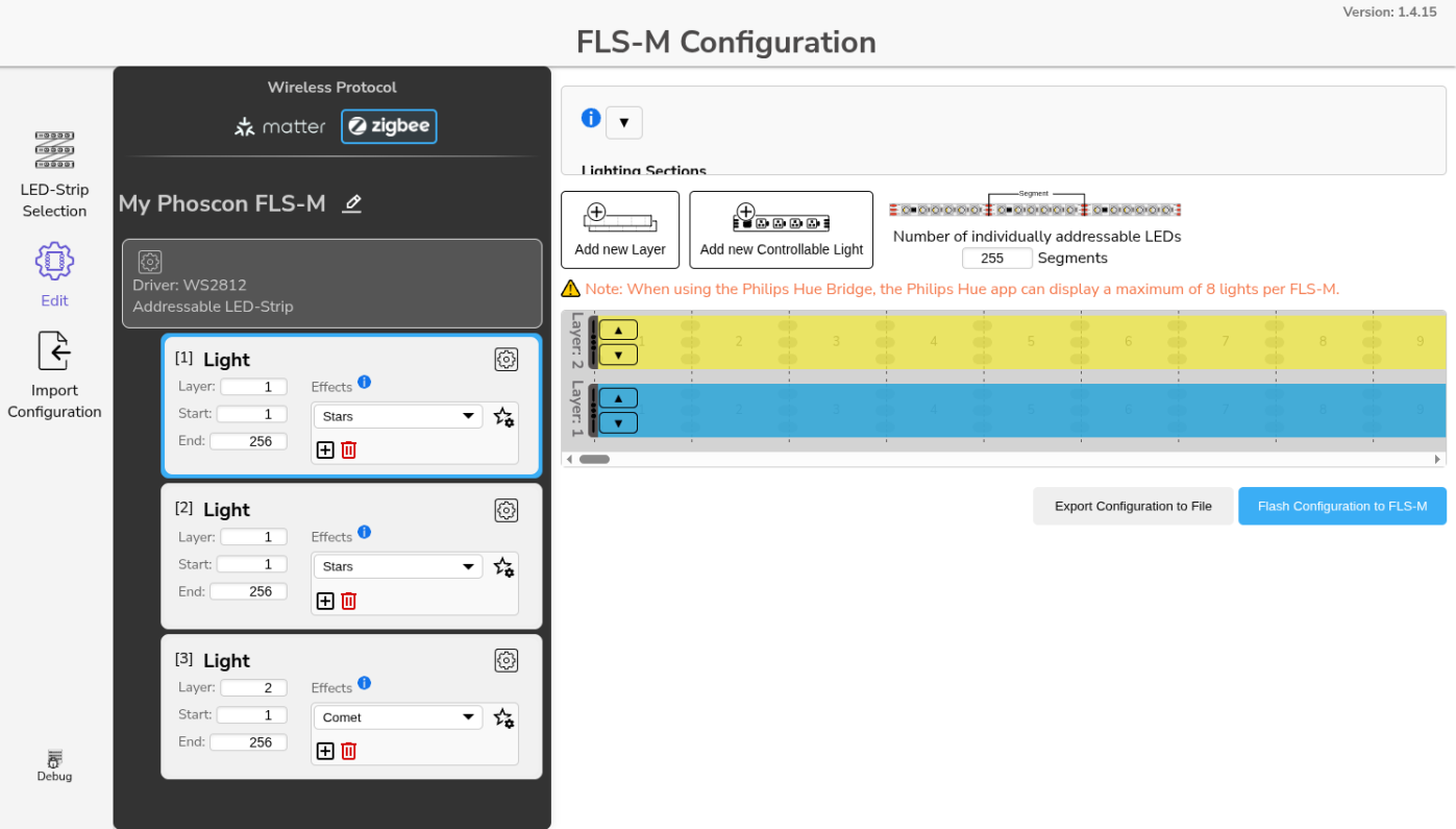
The following examples were created using a 16x16 LED matrix, consisting of 256 WS2812 LEDs. The color adjustment of the lights and animations is done exclusively via the Phoscon app. Any other Matter or Zigbee app can also be used.
Example: Stars and Comet
Setting:
- Total number of LED segments: 256
- Three lights, two with a
star
effect and one light with acomet
effect
Configuration:
Result:
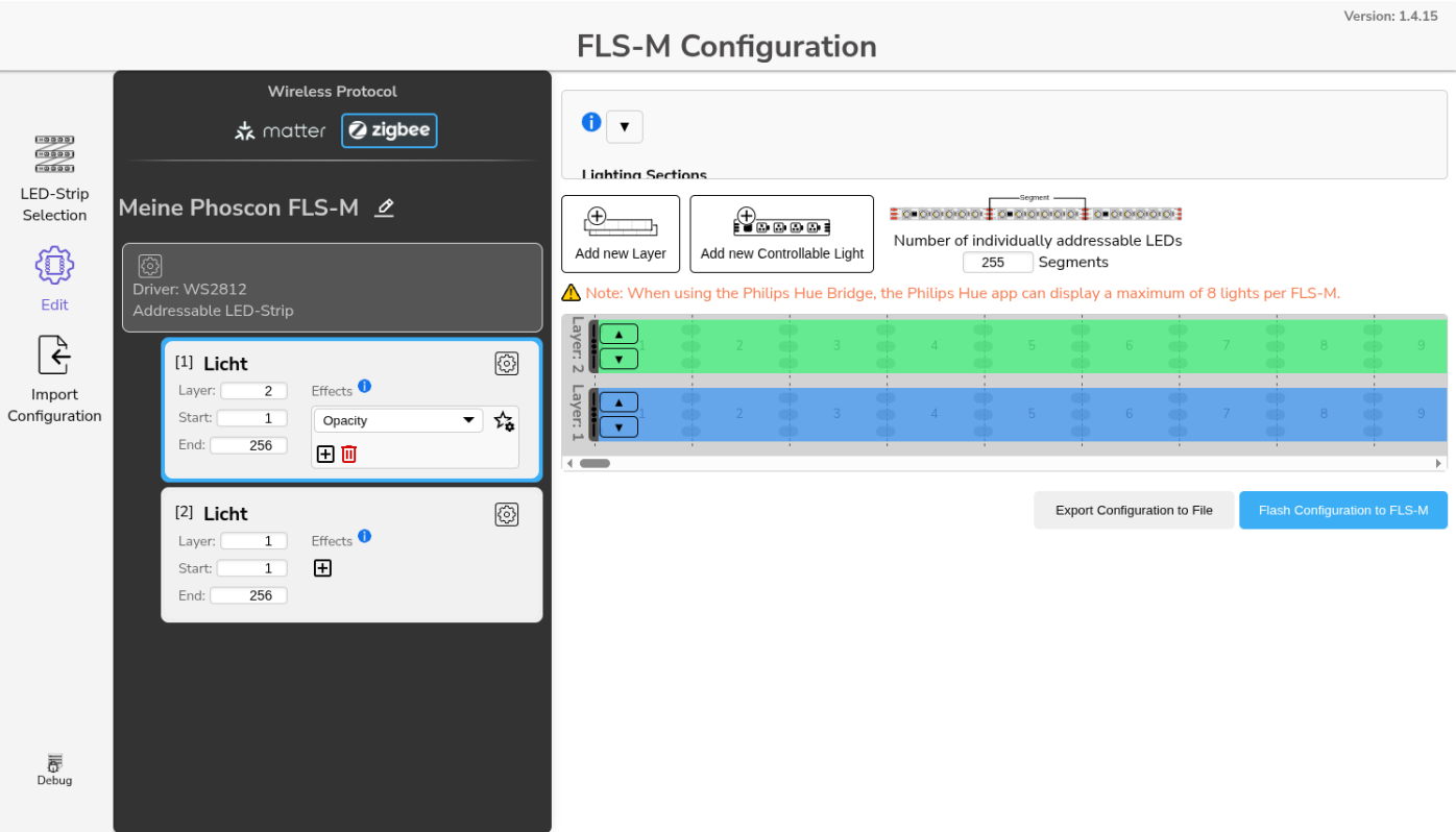
Example: Opacity
Setting:
- Total number of LED segments: 256
- Two lights, one with
Opacity
effect and the other static
Configuration:
Result:
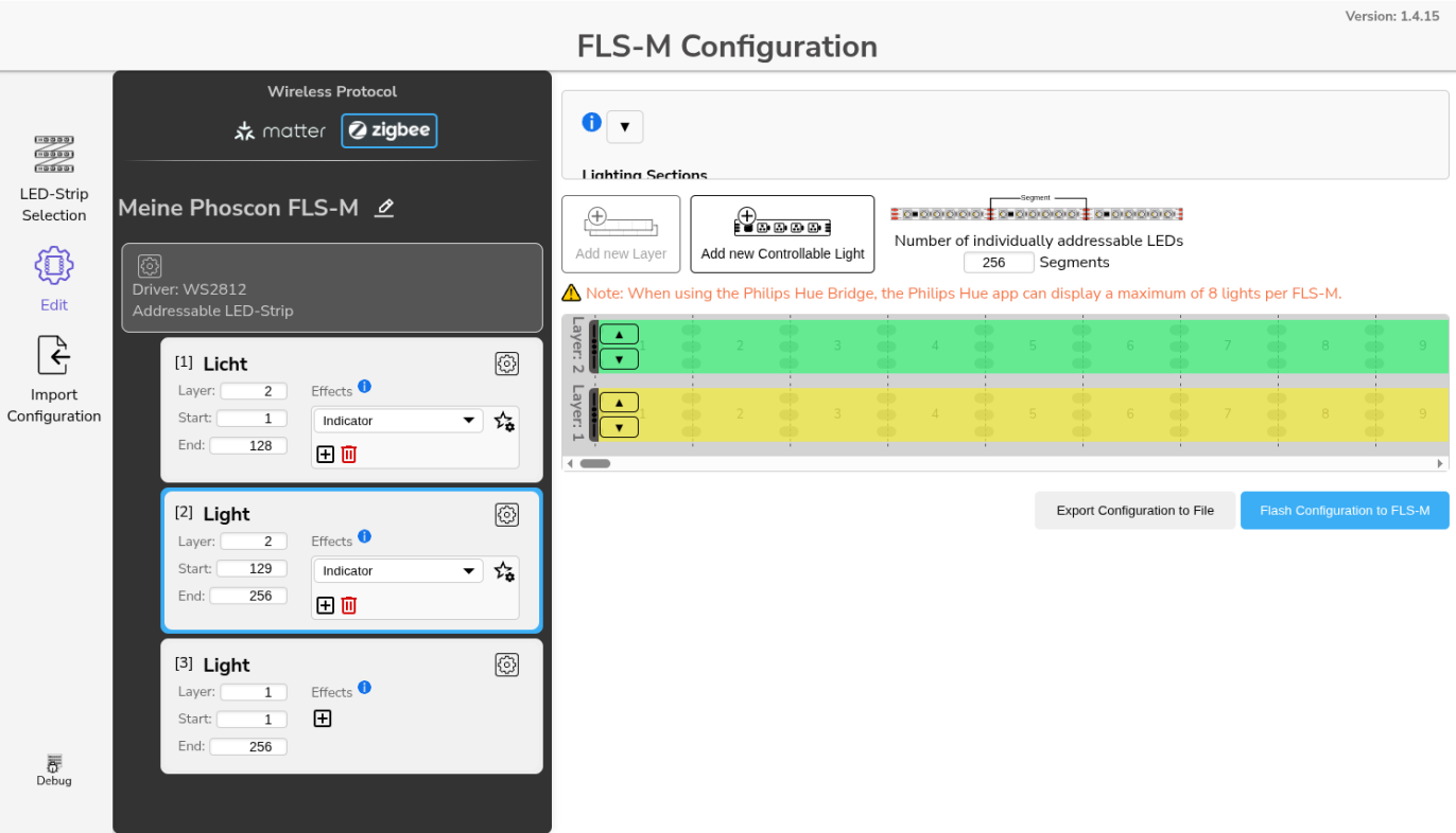
Example: Indicator
Setting:
- Total number of LED segments: 256
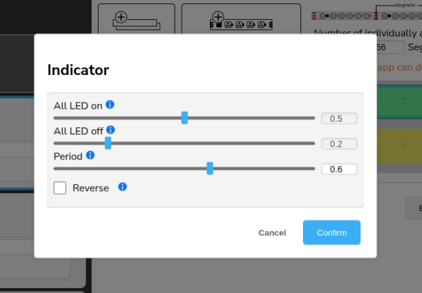
- Three lights, two with
Indicator
effect and the other static - The indicator always flashes once per second
Configuration:
Result:
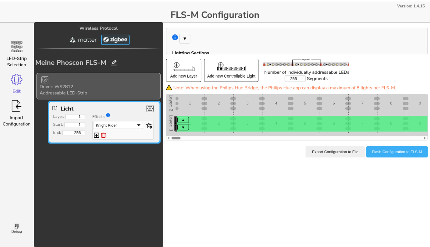
Example: Running Light
Setting:
- Total number of LED segments: 256
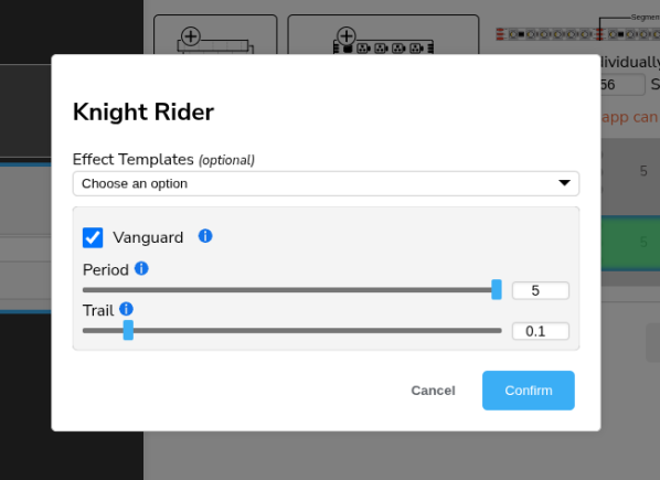
- One light with
Knight Rider
effect
Configuration:
Result:
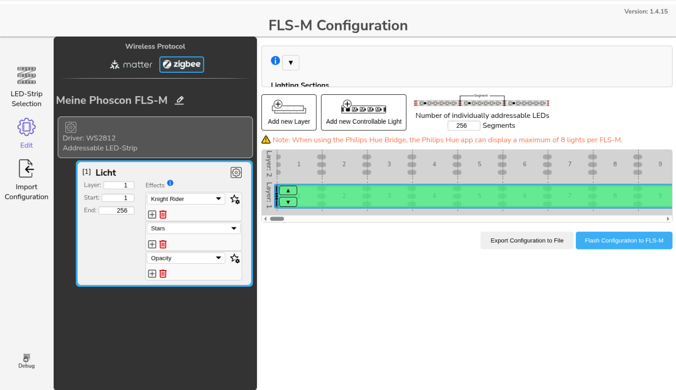
Example: Effect changer
Setting:
- Total number of LED segments: 256
- One light with
Knight Rider
,Stars
andOpacity
effects - By switching the light on/off in the respective Matter or Zigbee app, the effects are switched through one after the other
Configuration:
Result: